Shopping Cart
0 item(s) - $0.00Inquiry List
0 item(s) - $0.00- PLC
- HMI
- Drive
- Sensor
- IPC
- IGBT
-
PLC,HMI Cable
- - Allen- Bradley PLC Programming cable
- - OMRON PLC Programming cable
- - Proface PLC Programming cable
- - Schneider PLC Programming cable
- - SIEMENS Programming Cable
- - GE FANUC PLC Programming Cable
- - Hitachi PLC Programming Cable
- - IDEC PLC programming cable
- - MITSUBISHI PLC Programming Cable
- - VIGOR PLC programming cable
- - Panasonnic NAIS PLC Programming Cable
- - FUJI PLC Programming Cable
- - Delta PLC Programming Cable
- - EVIEW,WEINVIEW,EASYVIEW HMI Programming Cable
- - Kinco HMI download cable
- - LG PLC Programming Cable
- - MCGS HMI download cable
- - T-VERTER PLC Programming Cable
- - Emerson PLC Programming Cable
- - KOYO9 PLC programming cable
- - Hakko Touch Panel PLC
- - KEYENCE PLC programming cable
- - Cheap programming cable
-
Touch Glass, Membrane
- - SIEMENS HMI Touch Glass
- - SIEMENS Protective Film,Membrance
- - SIEMENS HMI Keypad
- - OMRON HMI Touch Glass
- - OMRON HMI Protective Film,Membrance
- - MITSUBISHI HMI Touch Glass
- - MITSUBISHI Protective Film,Membrance
- - FUJI Touch Glass
- - FUJI Protective Film,Membrance
- - FUJISTU HMI Touch Glass
- - Pro-face HMI Touch Glass
- - Pro-face Protective Film,Membrance
- - HAKKO HMI Touch Glass
- - HAKKO Protective Film Membrance
- - Delta HMI Touch Glass
- - HITECH HMI Touch Glass
- - PATLITE HMI Touch Glass
- - PATLITE HMI Protective Film Membrance
- - Nissei HMI Touch Glass
- - Panasonic HMI Touch Glass
- - Panasonic Protective Film Membrance
- - Koyo HMI Touch Glass
- - IDEC HMI Touch Glass
- - Schneider HMI Touch Glass
- - Allen Bradley PanelView Plus Touch Glass
- - Allen Bradley PanelView Plus Keypad
- - Allen Bradley PanelView Plus Protective Film Membrance
- - Allen Bradley PanelView Keypad
- - Allen Bradley PanelView Touch Glass
- - Allen Bradley PanelView Protective Film Membrance
- OEM S7-200/300 PLC
- Servo Cable
- Source code
- Fieldbus
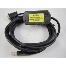
USB/PPI :Siemens S7-200 PLC Programming cable,replace 6ES7901-3DB30-0XA0
Availability: 102
Sold: 99
USB/PPI :Siemens S7-200 PLC Programming cable,replace 6ES7901-3DB30-0XA0
Introduction
USB/PPI programming cable simulates USB port as traditional serial port (usually COM3), which enables existing programming software(STEP7-MicroWin) to communicate through simulated traditional port and PLC
devices.
The working power of this cable is from USB port,not provided by the communication port of PLC.The LED of the adapter indicates the sending and receiving status of data.
USB/PPI is applied to Siemens S7-200 PLC,NOT support hot plug.For the industry scene of strong interference and easily destroying communication port,
pls choose optoelectronic isolated USB/PPI+ programming cable.
USB/PPI principle and figure structure:
.jpg)
| PIN | Signal | Description |
| 3 | RxD/TxD+ | Data signal B(RS485+) |
| 8 | RxD/TxD- | Data signal A(RS485-) |
| 5 | GND | GND |
Pin signal definition
Functions
ã Support Windows2000/Windows XP
ã Support STEP7 Micro/WIN V3.2 and higher
ã Fully compatible with USB V1.1 and USB CDC V1.1
ã Power supply by USB main line.current:about 50mA.
ã Baud rate: 300bps ÿ§ 1Mbps
ã Support long distance communication up to 2000m
ã Working temperature -20~+75'C
ã Length 3 meters.Color:black
ã One pc supports one USB programming cable only
System requirement
Please make sure your PC is IBM PC compatible and has the following
system requirements before using the USB programming cable.
ã Intel is compatible with 586DX4-100MHz CPU or higher
ã A standard USB port (4-pin A plug)
ã Operating system is Windows2000 or Windows XP
The setting of driver procedure
Please set the driver procedure according to the following steps:
1. Turning on PC power that will connect the USB programming cable and make sure the USB port working well.
2. Put the USB programming cable into USB port and Windows will detect the device and help to add new hardware and jump to new device setting.
Insert the driver CD and click ãnextã to continue, or select the driver on the hard disk.
If Windows does not show ãfind new hardwareã, please click ãUniversal Serial bus controllersã in the hardware list of device manager, and choose the USB
device with question mark. Click the right key of mouse and operate to update driver procedure.
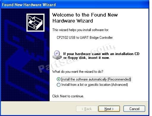
If insert the driver CD,you should select the recommended item and click ãNextã
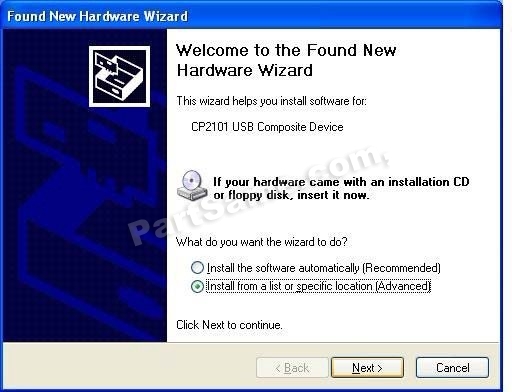
If the driver is saved on the hard disk, you should select the second item and click ãNextã. You can find the driver on the ãWINã folder.
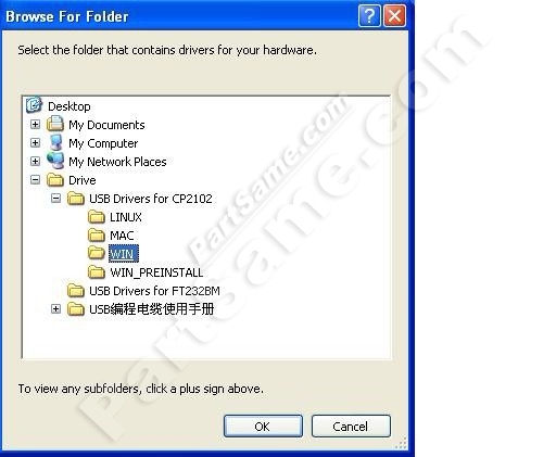
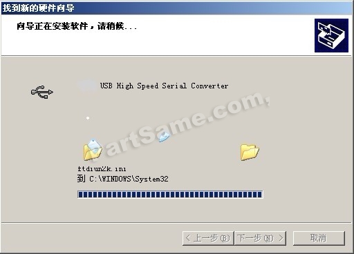
3. Windows will detect the setting information, and load the driver to install.
4. Continue to set up, copy the driver procedure files to your hard disk by Windows.
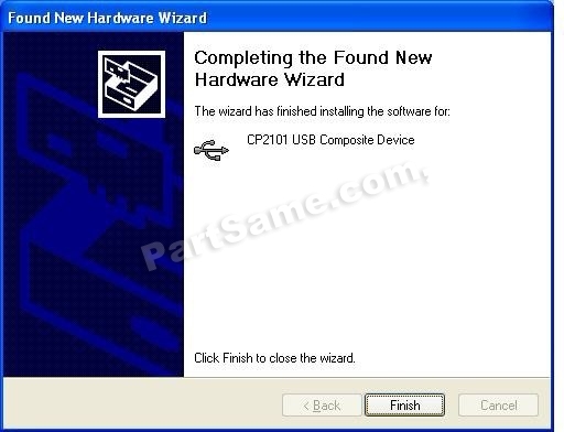
5. When Windows appears ãCompleting the Found New Hardware Wizardã, click ãfinishã to end setting up.
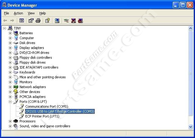
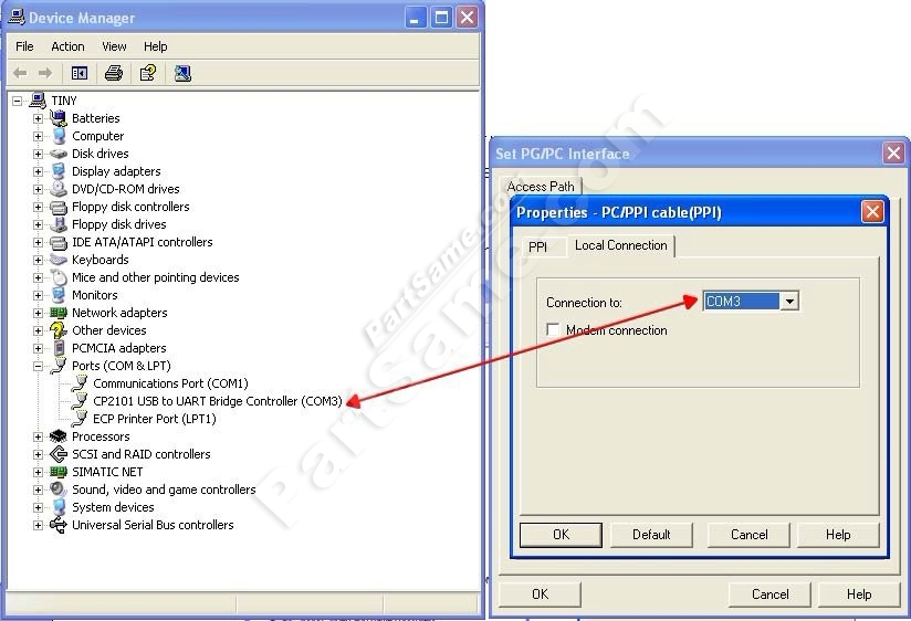
6. After setting up, please make sure the "port (COM and LPT)" of "Start \Settings \ Control Panel \ system \ hardware \ Device Manager" appears
"CP2101 USB to UART Bridge Controller(COMx)". This COMx is the COM message of the USB programming cable.
From then on, as long as you insert the programming cable, the COM port will appear.
You just have to choose this COM port in application software such as programming software or communication software.
The deletion of driver procedure
Deleting driver procedure is to discharge source of COM port so that other
device can be used. When driver procedure has error, it should be deleted and reset up. Please delete the driver procedure as follows:
1. Unplug the USB programming cable from you PC.
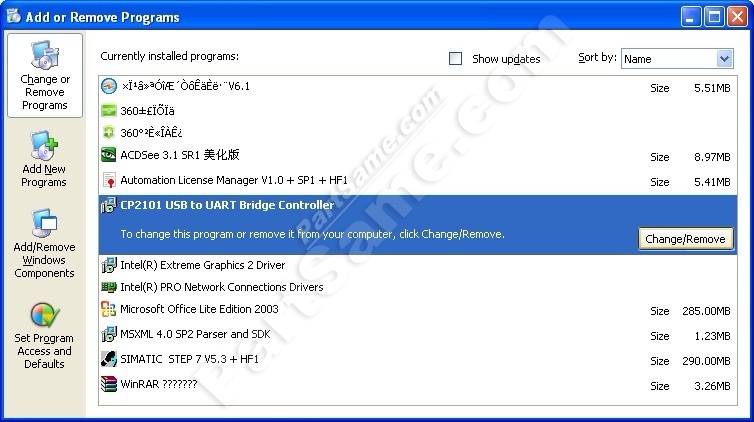
2. Choose ãUSB Serial Converter Driversãfrom "Add or Delete Programsã in operation panel, and click the ãChange/Removeã button.
How to change COM setting
1. Delete the driver procedure of all USB to UART products to discharge COM port source, and reset up USB programming cable driver procedure.
The device manager will display the cable address COM3.
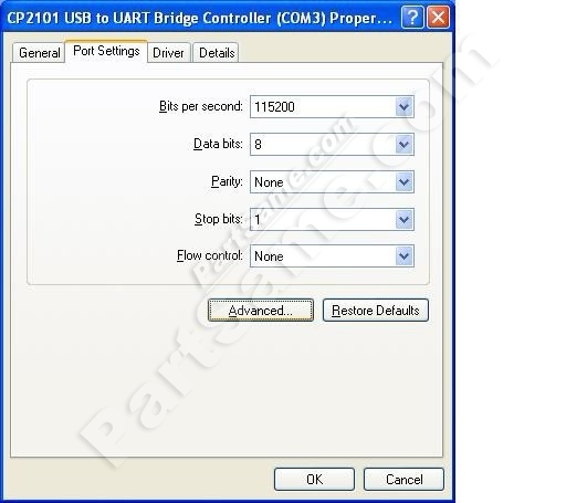
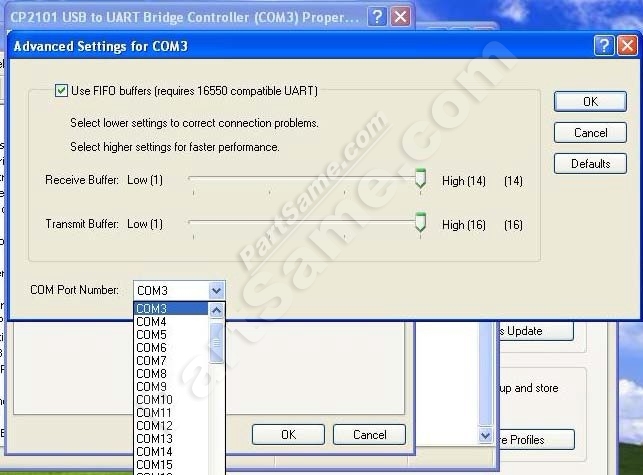
2. In Windows 2000/XP the COM slogan can be changed directly. Please double click COM port device that is need changing in the device manager,
and the device attribute information window will appear. Choose ãport settingã as the picture shows. Click "Advanced" button,
and the advanced setting information window will appear. Set the COM port to the serial number you want and click "OK" button to complete.
Setting of Step 7-MicroWin
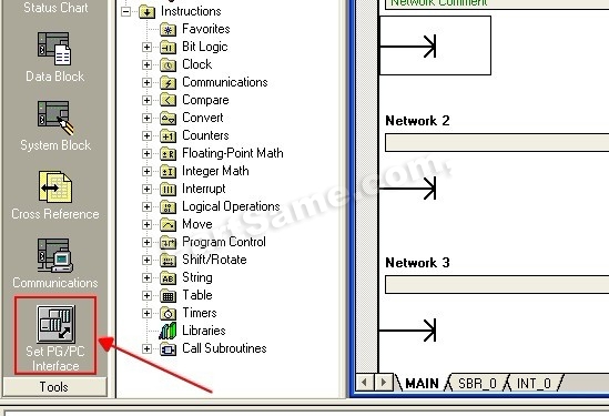
Open the main windows form(Step7-MicroWin)ÿ¥ click ãSet PG/PC Interfaceã of the left view and will appear PG/PC setting window.
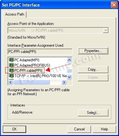
1.Double click ãPC/PPI cable(PPI) ã to open COM port and PPI port parameter setting dialog box.
2.Click ãLocal Connectionã to set COM port parameter, choose correctly COM port in the device manager after install the driver,
and set the transmission rate as 9600bps or 19200bps,which is both OK, then the USB/PPI will adapt the baud rate automatic.
About Long Distance Communication
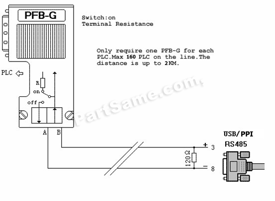
For USB/PPI, the largest communication distance is up to 2000m at the communication speed of 9600bps.
It needs to splice 120ohm terminal resistance between 3 and 8 pin on the RS485 port(DB9 Male) to eliminate signal reflection.
But requires one PFB-G for each PLC.
Notes and Troubleshoot
1. If the USB programming cable could not be detected when opening the PC, or some other outstanding issues occur, please replug it again.
2.USB to UART is plug and play USB device. When data are being transmitted,please donãt disconnect it.
3. Sometimes when Windows System failures or outstanding issues when plug or unplug the USB cable occur, please restart the computer and PLC.
4. USB/PPI cable donãt support ãUSBã interface in the Step7-MicroWin,so you should choose ãCOMã port.
5. If the COM port with ã*ã symbol in the software,such as ã*COM3ã,it indicates this COM port is at fault,pls exit programming software and then replug the USB port or reinstall the USB driver.
6. It doesnãt support 187.5Kbps baud rate.
Rejection provision
This document is to provide information, and the contents will not be noticed when revising. Because of the direct or indirect loss or errors caused by revised document,
will not be the responsibility of the manufacturer.
Package Includes:
OEM Siemens S7-200 USB PPI PLC Cable X 1
Write a review
Your Name:Your Review: Note: HTML is not translated!
Rating: Bad Good
Enter the code in the box below:


