Shopping Cart
0 item(s) - $0.00Inquiry List
0 item(s) - $0.00- PLC
- HMI
- Drive
- Sensor
- IPC
- IGBT
-
PLC,HMI Cable
- - Allen- Bradley PLC Programming cable
- - OMRON PLC Programming cable
- - Proface PLC Programming cable
- - Schneider PLC Programming cable
- - SIEMENS Programming Cable
- - GE FANUC PLC Programming Cable
- - Hitachi PLC Programming Cable
- - IDEC PLC programming cable
- - MITSUBISHI PLC Programming Cable
- - VIGOR PLC programming cable
- - Panasonnic NAIS PLC Programming Cable
- - FUJI PLC Programming Cable
- - Delta PLC Programming Cable
- - EVIEW,WEINVIEW,EASYVIEW HMI Programming Cable
- - Kinco HMI download cable
- - LG PLC Programming Cable
- - MCGS HMI download cable
- - T-VERTER PLC Programming Cable
- - Emerson PLC Programming Cable
- - KOYO9 PLC programming cable
- - Hakko Touch Panel PLC
- - KEYENCE PLC programming cable
- - Cheap programming cable
-
Touch Glass, Membrane
- - SIEMENS HMI Touch Glass
- - SIEMENS Protective Film,Membrance
- - SIEMENS HMI Keypad
- - OMRON HMI Touch Glass
- - OMRON HMI Protective Film,Membrance
- - MITSUBISHI HMI Touch Glass
- - MITSUBISHI Protective Film,Membrance
- - FUJI Touch Glass
- - FUJI Protective Film,Membrance
- - FUJISTU HMI Touch Glass
- - Pro-face HMI Touch Glass
- - Pro-face Protective Film,Membrance
- - HAKKO HMI Touch Glass
- - HAKKO Protective Film Membrance
- - Delta HMI Touch Glass
- - HITECH HMI Touch Glass
- - PATLITE HMI Touch Glass
- - PATLITE HMI Protective Film Membrance
- - Nissei HMI Touch Glass
- - Panasonic HMI Touch Glass
- - Panasonic Protective Film Membrance
- - Koyo HMI Touch Glass
- - IDEC HMI Touch Glass
- - Schneider HMI Touch Glass
- - Allen Bradley PanelView Plus Touch Glass
- - Allen Bradley PanelView Plus Keypad
- - Allen Bradley PanelView Plus Protective Film Membrance
- - Allen Bradley PanelView Keypad
- - Allen Bradley PanelView Touch Glass
- - Allen Bradley PanelView Protective Film Membrance
- OEM S7-200/300 PLC
- Servo Cable
- Source code
- Fieldbus
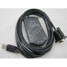
USB/PPI+:optoelectronic isolated USB/PPI adapter for S7-200,replace 6ES7901-3DB30-0XA0
USB/PPI+:optoelectronic isolated USB/PPI adapter for S7-200,replace 6ES7901-3DB30-0XA0
Introduction
USB/PPI+ programming cable simulates USB port as traditional serial port (usually COM3), which enables existing programming software(STEP 7-MicroWin) to communicate through simulated traditional port and PLC devices.
The working power supply of this cable is from the USB port and PLC programming interface. The two-color LED on the converter box indicates dataãs transceiving status.
USB/PPI+ is optoelectronic isolated,suitable for Siemens S7-200 series PLC,especially for the strong interfere and easily damaged communication interface industry scene.The safeguard in the circuit guarantees the safely running of the system.
USB/PPI+ principle and figure structure:
|
PIN |
Signal |
Description |
|
3 |
RxD/TxD+ |
Data signal B(RS485+) |
|
8 |
RxD/TxD- |
Data signal A(RS485-) |
|
7 |
P24V |
24V power positive |
|
2 |
M24V |
24V power negative(RS485 logic ground) |
signals definition of the RS485-Block (DB9M) of the USB/PPI+
Functions
- Support Windows2000/Windows XP
- Support STEP7 Micro/WIN V3.2 and higher
- Fully compatible with USB V1.1 and USB CDC V1.1
- Power supply by USB bus and PLC programming port.
- Baud rate: 300 bps ~ 1Mbps automatically adapt to the standard baud rate.
- Support UART data format: data bits: 7-8; stop bit: 1, 2; check-bit: odd / even / no parity
- Support long distance communication up to 2000m(9600 bps).
- Working temperature -20~+75'C
- Length 3 meters.Color:black
- One pc supports one USB programming cable only
System requirement
Please make sure your PC is IBM PC compatible and has the following system requirements before using the USB programming cable.
- Intel is compatible with 586DX4-100MHz CPU or higher
- A standard USB port (4-pin A plug)
- Operating system is Windows2000 or Windows XP
The setting of driver procedure
Please set the driver procedure according to the following steps:
- Turning on PC power that will connect the USB programming cable and make sure the USB port working well.
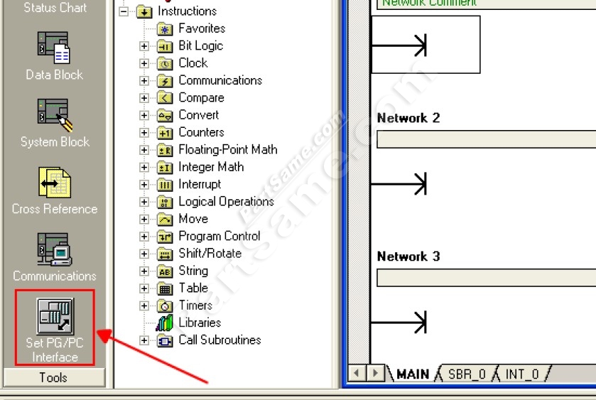
- Put the USB programming cable into USB port and Windows will detect the device and help to add new hardware and jump to new device setting. Insert the driver CD and click ãnextã to continue, or select the driver on the hard disk.
If Windows does not show ãFound New Hardware Wizardã, please click ãUniversal Serial bus controllersã in the hardware list of device manager, and choose the USB device with question mark. Click the right key of mouse and operate to update driver procedure.

Write a review
Your Name:Your Review: Note: HTML is not translated!
Rating: Bad Good
Enter the code in the box below:


